
DISCLAIMER! Anything YOU do to YOUR bike is YOUR responsibility! I hearby absolve KawiForums, myself and any other person I recieved input from to do this. If you do follow this and decide to do this to YOUR bike, it is of YOUR own free will. If YOUR bike catches fire because YOU wired it wrong, YOU are on YOUR own.
That being said I'll begin.
Step 1:
Disconnect the battery using a #3 Phillips head screwdriver, or the appropriate socket with a ratchet. (Please ignore the CDI placement, it's temporary. I apologize for the filthy bike.)


If you do not disconnect the battery, you risk shorting out your electrical system. This step is a MUST.
Step 2:
Remove Windscreen. This will allow all the access you need to perform the whole swap, start to finish.
Step 3:
Pull rubber cover off of Gauge's back to reveal the guage wiring harness.

Push down on holding clip located on top of the connector. Gently pull back and wiggle left to right to remove.

Step 4:
Using an 8mm open end wrench, remove the three nuts holding the gauge cluster securely in place.

Step 5:
Here's where the Fun (nightmare?) begins.
Using a small flat head screwdriver, gently pry the back outside walls of the connector. This will allow you to lift both of the retaining flaps on the connector.


Step 6:
Removing the pin connector wires from the Connector Harness-
You will need a JUMBO paper clip. Bend the long outside part to a little past 45 degrees.
I will be referring to the harness as the retaining clip being on top at all times and looking at it from the wire side.
All of the wires go in one way. You will be inserting the paper clip through a "box" above the wire. The clipwill go in about 3/4 of an inch. This will depress the retainer inside the slot allowing you to remove the wire. Gently pull back on the wire along with the clip at the same time.
If the wire doesn't budge, pull out the clip and try again. BE GENTLE. I've had to try 5 times with one wire, but eventually it came out.
Crude cross section drawings to give you an idea of what's taking place:

I removed all the top wires first, left to right.

I then removed all the bottom wires, left to right; EXCEPT the bottom right yellow wire. This stays in the same location and is a good starting point for reattaching the wires.

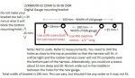
Here is a diagram of the stock wires and what each wire is for:
Step 7:
Inserting wires in new location.
I worked right to left this time, bottom to top. You must insert the wires flat side down. Going off of this diagram, start from 16 and place the RED wire with BLACK STRIPE in 15's slot, working your way counting backwards. This allows you to rearrange the wires in the electrical tape to suit their new location.
Here is the new wire location for the 03-06 guages:

I made a jumper pin from my paper clip to connect the two ground wires in #9 slot. (This will allow for replaing the stock gauges, if this isn't a concern you can simpyly slice the two together)

Now when all the wires are in their new place and you've triple checked, close the upper and lower retaining flaps. The connector is now compatible with the new gauges, sans a few minor things I will address at the end.
Without a fuel level sending unit, the fuel light will flash constantly. On the 05-06 gauges it also says FUEL in the odometer area. This is VERY annoying. On the 05-06 gauges you can simply place the leftover 12v RED with BLUE STRIPE wire into slot #2 and it will stay off. The 03-04 gauges use a different sending unit, so this trick doesn't work. I took hole puch and puched a small circle of electical tape and removed the cover off of the gauges. (5 phillips screws on back).


You could also remove the yellow LED from inside if you feel so inclined.
Step 8:
Mounting.
Since this is custom, you can place the gauge any way you want, at any angle.
I preffer a "stock" look to things and took this route-
Using a stock liscense plate bracket, I drilled the slots closer together and screwed in the top 2 mounts on the guage from behind. I picked up black screw caps at the hardware store to clean the look up. I then screwed in the bottom mount in the stock position. With this done, I used 2 extra fairing screws I had and 2 stock mounting nuts from the other gauge cluster to secure the liscense plate bracket to the top stock mounting points. It is very secure and looks almost like it came factory this way.


Step 9;
Plug in the connector, reconnect the battery and reinstall the wind screen and you're done!
Minor issues:
You won't have a temp reading until you replace the stock sending unit with a 03-06 636 one. This requires drilling in the engine and retapping [B)]. Definately not a shadetree mechanic job. Too much can go wrong.
The fuel light is no concern, if you have a J model you should be used to not having it.
The stop watch and lap timer don't work, but can be with a couple push button switches installed.
Although the wiring is identical for the harness from 03-06, there are a few differences-
If you use an 03-04 gauge the speed sensor is the same and the seedo will work.
If you use an 05-06 guage you'll need a speedo healer, as the sensor is different and it will read 4 MPH when your going 50 MPH actual.
03-04 gauges:

05-06 gauges

That's it! Hope this was helpful, this was my first (and possibly last) How To write up. Big thanks to Tazman!
Ben
That being said I'll begin.
Step 1:
Disconnect the battery using a #3 Phillips head screwdriver, or the appropriate socket with a ratchet. (Please ignore the CDI placement, it's temporary. I apologize for the filthy bike.)
If you do not disconnect the battery, you risk shorting out your electrical system. This step is a MUST.
Step 2:
Remove Windscreen. This will allow all the access you need to perform the whole swap, start to finish.
Step 3:
Pull rubber cover off of Gauge's back to reveal the guage wiring harness.
Push down on holding clip located on top of the connector. Gently pull back and wiggle left to right to remove.
Step 4:
Using an 8mm open end wrench, remove the three nuts holding the gauge cluster securely in place.
Step 5:
Here's where the Fun (nightmare?) begins.
Using a small flat head screwdriver, gently pry the back outside walls of the connector. This will allow you to lift both of the retaining flaps on the connector.
Step 6:
Removing the pin connector wires from the Connector Harness-
You will need a JUMBO paper clip. Bend the long outside part to a little past 45 degrees.
I will be referring to the harness as the retaining clip being on top at all times and looking at it from the wire side.
All of the wires go in one way. You will be inserting the paper clip through a "box" above the wire. The clipwill go in about 3/4 of an inch. This will depress the retainer inside the slot allowing you to remove the wire. Gently pull back on the wire along with the clip at the same time.
If the wire doesn't budge, pull out the clip and try again. BE GENTLE. I've had to try 5 times with one wire, but eventually it came out.
Crude cross section drawings to give you an idea of what's taking place:
I removed all the top wires first, left to right.
I then removed all the bottom wires, left to right; EXCEPT the bottom right yellow wire. This stays in the same location and is a good starting point for reattaching the wires.
Here is a diagram of the stock wires and what each wire is for:
Step 7:
Inserting wires in new location.
I worked right to left this time, bottom to top. You must insert the wires flat side down. Going off of this diagram, start from 16 and place the RED wire with BLACK STRIPE in 15's slot, working your way counting backwards. This allows you to rearrange the wires in the electrical tape to suit their new location.
Here is the new wire location for the 03-06 guages:
I made a jumper pin from my paper clip to connect the two ground wires in #9 slot. (This will allow for replaing the stock gauges, if this isn't a concern you can simpyly slice the two together)
Now when all the wires are in their new place and you've triple checked, close the upper and lower retaining flaps. The connector is now compatible with the new gauges, sans a few minor things I will address at the end.
Without a fuel level sending unit, the fuel light will flash constantly. On the 05-06 gauges it also says FUEL in the odometer area. This is VERY annoying. On the 05-06 gauges you can simply place the leftover 12v RED with BLUE STRIPE wire into slot #2 and it will stay off. The 03-04 gauges use a different sending unit, so this trick doesn't work. I took hole puch and puched a small circle of electical tape and removed the cover off of the gauges. (5 phillips screws on back).
You could also remove the yellow LED from inside if you feel so inclined.
Step 8:
Mounting.
Since this is custom, you can place the gauge any way you want, at any angle.
I preffer a "stock" look to things and took this route-
Using a stock liscense plate bracket, I drilled the slots closer together and screwed in the top 2 mounts on the guage from behind. I picked up black screw caps at the hardware store to clean the look up. I then screwed in the bottom mount in the stock position. With this done, I used 2 extra fairing screws I had and 2 stock mounting nuts from the other gauge cluster to secure the liscense plate bracket to the top stock mounting points. It is very secure and looks almost like it came factory this way.
Step 9;
Plug in the connector, reconnect the battery and reinstall the wind screen and you're done!
Minor issues:
You won't have a temp reading until you replace the stock sending unit with a 03-06 636 one. This requires drilling in the engine and retapping [B)]. Definately not a shadetree mechanic job. Too much can go wrong.
The fuel light is no concern, if you have a J model you should be used to not having it.
The stop watch and lap timer don't work, but can be with a couple push button switches installed.
Although the wiring is identical for the harness from 03-06, there are a few differences-
If you use an 03-04 gauge the speed sensor is the same and the seedo will work.
If you use an 05-06 guage you'll need a speedo healer, as the sensor is different and it will read 4 MPH when your going 50 MPH actual.
03-04 gauges:
05-06 gauges
That's it! Hope this was helpful, this was my first (and possibly last) How To write up. Big thanks to Tazman!
Ben