Kawasaki Motorcycle Forums banner

06/06 ZX636 ZX6R speedo upgrade and TRE

234K views 533 replies 187 participants last post by  gavinvandertoorn  
#1 · (Edited)
05/06 ZX636 ZX6R speedo upgrade

Hello everyone.

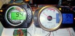
A while ago there was a big discussion on how to fit a P7 style ZX6 speedo onto an older model bike (typically the 05/06 C1H model).

The main reason for doing this was to have the nice white dial easily readable clocks instead of the quite trick but less clear LCD type.

Well the long and short of it was that you could replace the speedo (indeed the mounting bolts are exactly the same for both models) so long as you made up an adapter (because the speedo used a different connector on the new model). However you had to put up with an annoying flashing warning light caused by no ECU communication to the clocks. The only solution at the time was to tape over the light, but then you wouldn't have the benefit of any real warnings.

At long last I've got around to reverse engineering the communication signal between a P7 ECU and a P7 speedo. The idea is we fit a little micro chip circuit to fool the new speedo and make it all work perfectly on an 05 ZX636. In fact, not only does the warning light behave, but we can also make the gear indicator work properly (ie make a TRE type gadget) too.

I don't expect this to be much use to most folks, but I wanted to put the info into the public domain as its apparently not known. You would need to be an electronics engineer to make use of this stuff.

OK, here we go with part1. The signals:

The speedo ECU comms line has a built in pull-up resistor to 10v so to inject a signal we need an open collector drive.
The comms line is normally HI (9.8v or so)
Data is sent in three packets at 10ms period between the start of each data byte.
The data signal is repeated at a period of 80ms (or roughly 60ms from the end of one packet to the start of the next).
If the data is interrupted, then after a few seconds the speedo will report a FI error and do the flashy red light (LED) thing, so we need to keep the data packets going continuously.
The data starts only when the ignition is turned on.
The three packets of data are all serial 8 bits plus one start bit (lo). The period of each bit is 64us.
(The following data is written as if it were a timing diagram)

1st gear ...10100000001..(10ms)..10000000001..(10ms)..10100000001..(60ms)..
2nd gear ...10010000001..(10ms)..10000000001..(10ms)..10010000001..(60ms)..
3rd gear ...10110000001..(10ms)..10000000001..(10ms)..10110000001..(60ms)..
4th gear ...10001000001..(10ms)..10000000001..(10ms)..10001000001..(60ms)..
5th gear ...10101000001..(10ms)..10000000001..(10ms)..10101000001..(60ms)..
6th gear ...10011000001..(10ms)..10000000001..(10ms)..10011000001..(60ms)..

So for 1st gear, if we monitor the speedo to ECU signal line (on a P7 speedo to P7 ECU of course) then we see the signal go to 0v for 64us then 9.8v for 64us then 0v for 448us then back to 9.8v
There is then a gap of 10ms (less 576us) to the middle packet which is a null frame: 0v for 576us
After another gap of 10ms (less 576us) the first data byte is repeated.
The data line is then inactive (still at 9.8v) for around 60ms until the whole thing is repeated.
(In the data sequence shown, dots represent where the data line is at a steady 9.8v level)

The speedo uses these data packets to continually verify the comms to the ECU, but of course these also represent what gear we are in.
So long as any of these 3 byte data packets are being sent then the FI/red LED will not be activated due to comms fail.
If the bike is in neutral then no gear is shown on the LCD part of the speedo.
If the bike is in gear then the LCD segment shows gear 1-6 depending on what data packets are being sent on the ECU comms line.

We are now in a position to make our own automatic gear indicator using engine RPM and wheel tacho signal. This is done by dividing the engine RPM count by the wheel tacho count. Both these signals already go to the speedo for displaying speed and revs.

OK, so I'll follow this up with a part2: cheap hardware to do all the signal controls.
Finally part3: this will be the software to program into a PIC micro.

Cheers

Extr400
 
Discussion starter · #6 ·
05/06 Clocks upgrade to P7 - nearly there!!!

OK,
So been busy with a micro development kit all weekend and have now completed the first part of the software to quench the FI light and get the gear info working in the P7 clocks.
At the moment have a little test program running to prove my kid-on ECU communication to the speedo. It cycles through all the gear codes so the display can be verified.

Good news is everything working good. No FI error or red LED. Gear selection readout is stable and glitch free. Have posted a picture here. This is such a super trick upgrade :)

Have to write some more code next to use the revs and speed to calculate the gear. Also need to rescale the speed pulse as the gearbox ratios are different for the new clocks.

Have based the electronics on a cheap Microchip development kit / programmer, but I think it will be possible to use a home made programmer (like Pony Prog) which only costs $10 to build.
 

Attachments

Discussion starter · #12 ·
Hi Lemmon1-
Lets see how this thing turns out. If I get enough interest I may design a custom PCB to act as a plug adapter + micro board. It only need be slightly bigger than the connector outline.
Had thought of the gearing issue: could provide an option for a 1xtooth smaller front sprocket. Anything more complex in terms of gear ratio can easily be catered for by options in the software.

Remember this is effectively a speedo healer as well, so you don't need anything else.

Had not thought of the tacho red line, but the shift light will work ok. Will have a think about this.

Cheers
Extr400
 
Discussion starter · #20 ·
Ok, time for another update.

Now have the speed signal conversion working. I'm testing with the old and new speedo but the new clock has my circuit doing the conversion.

Scale factor is to divide frequency by 4.2211 (hmm, if your interested - the service manual for the P7 clocks appears to give the wrong tacho test info). In fact my software allows almost any scale factor with a very high degree of accuracy.

At the moment, the scale factor number is hard coded in (meaning you can't change it) but am thinking of having an external push button to allow an adjustment function. This would make it easy to cope with any gearing change without having to go away and reprogram the micro.

Out of interest I put a signal into the tacho pin of each speedo. Its a bit rubbish that both read on the hi side. The C1H is 6% rpm too fast and P7 reads 2.5% rpm too fast (the input signal was 13,140 rpm) - anyone else noticed this? It does compound the problem of the shift light being triggered at 14k on the old speedo and 15k on the new one. Have just about exhausted all the functions of the tiny micro that I chose for this project but there may be a bit left to do a tacho healer too!

Still have to calculate the gear from the speed and tacho signals and then I can feed this into the bit that sends the digital code to the clocks ECU pin. Incidentally, this is independent of any final drive gearing, because it uses the signals directly from the engine pick-up (and before being re-scaled). So if you change sprockets the gear indicator will still read correctly.

If anyone wants to get ahead of the game and build one of these, you could do worse than order yourself a pickit2 from Microchip (available direct or through Digikey.com in the USA or Farnell.co.uk here at home. There are also copy versions on ebay). You will also need the specific micro which is a PIC12F683. Will post a zip file of the circuit board and software files soon as its all tested.

One final note, its true that if you feed a scaled down speed signal into the ECU itself, then you will proportionately INCREASE any speed limiting function within the ECU. However this may also affect the ignition mapping so care must be taken. Personally I'm only using the circuit described here to alter the signals to the clocks - not to the ECU as well.

Extr400
 

Attachments

Discussion starter · #21 ·
Nice work!

If it's not of hard work, I wish you'll save the code that does not heal the speedo. As 03/04 and 07/08 kawis use same speedo input no healing is needed.

And I'm just throwing this: if you run other gearing than stock but catch the rpm and speed input (speedo will be off) won't it calculate the gear right? And if you would use something like a speedohealer AFTER the gear has been calculated, you would also have correct speed on the speedo? So that would address the problem with gearind changes...
Hi markketo.
I've had a look at the service manual for the 03/04 model and it looks like the speedo signal is completely different to the P7 (though the data on the P7 is also wrong in my copy):
03/04 speedo : 60mph @ 146Hz engine signal
04/05 speedo : 60mph @ 1168Hz engine signal
06/07 speedo : 60mph @ 276Hz engine signal (service manual says 840Hz)

I'm working in Miles rather than Km but the difference remains.

In addition the book says 3rd gear is a different ratio between 03/04 and 05/06. Am fairly certain the new model is very different gearing to either old bikes.

Have already mentioned that the final drive gearing is not an issue.

The 05/06 bikes use a dedicated FI line from the ECU to the speedo. Since this is also present on the P7 clocks then I'm assuming the normal FI error codes will still be reported correctly. Have to check this of course!

Extr400
 
Discussion starter · #32 ·
Been away on a surf trip (no motorbikes involved) to not so sunny but very wet north west Ireland. After a week of throwing myself in cold sea water, am now back on the case.

Have been looking at correcting the tacho signal in the same way as the speed signal. Trouble is the resources are at a max inside the little pic micro. I suppose I could just use two micro's but that wouldn't be very elegant. At the moment I'm going to just punt the same tacho pulses back out on a different pin on my chip. Maybe I can find a solution at a later date and post a software update to fix it.

Have also been looking into connectors to allow a plug and play solution for this project. The ZX6 LCD clocks use a 16 pin AMP connector but I can't find the part number on the Tyco Electronics website. The new analog tach clock uses a JAE 20 pin part (the harness side part number is MX34020SF1). The connector shells are quite cheap but I have to buy the crimp pins on a whole reel of 7000 which cost a fortune. Anyone know of a supplier for these selling just a few hundred, please send me a message. There may be a way around this problem by making the PCB be the connector shell. I'll post pictures of what I mean in due course.

Am just tuning up the software so the gear display is good for any gear/speed. I'll post a list of components/part numbers, the circuit diagram and the basic software in a week or so.

Anyone interested in buying a plug and play solution, please mention it on this post. It will give me some idea of what kit of parts to buy in. I would expect to sell built up and tested adapters for around $40 if your not up for building one yourself (most of the expense is in getting a circuit board manufactured and the cost of connectors).

More soon.
Extr400
 
Discussion starter · #43 ·
OK, time for a progress report.
Its getting exciting now. Have finished the mk1 software and selected the gear change ratios for our bikes gearbox and standard sprocket sizes. Have done the circuit diagram and its all set to publish.
Have even found where to buy all the connectors - the 16way original tacho connector is available form RS Components stock number 362-8904. The 20way P7 tacho header (wiring loom side) is from Mouser.com part number 656-MX34020SF1 but they only sell gazillions of the crimp pins you need for it, so get those from Digikey p/n M34S75C4F1-ND.
These are the difficult bits as far as I'm concerned, as without the connectors you have to hack the wiring loom which is never a good thing. Have ordered up enough parts for a build of 25 units.
This weekends job is to follow my own instructions, taking photos along the way, of how to build one of these prototypes. This is a good way of discovering all those little problems and mistakes. I'll then post all the info on this thread.

Have already started adding in those crucial features like you get in commercial products. This will let you adjust the speed scale and gear select points via a push button sequence. Hey, I design this stuff for a living, so your getting the real mcCoy!

There is a difference in the number of warning LEDs between the two speedos in that the newer one is missing the oil pressure warning LED. This is dealt with by combining the FI and oil pressure signal to the single FI LED on the P7 clocks. You have to use diodes on each line when connecting them together (it won't work proper unless you do). This is what I've done on the prototype and seems to work well.

If nothing else, all this is a cheap way of getting a speedo healer, regardless of your bike model. Which is a good point actually, some people are missing the fact this adapter does that function too. Hmmm, might pre-empt those that don't want the healer function and allow a disable function.

Also to do is design a custom circuit board for the plug and play solution. Should make the adapter be small as possible - basically two connectors back to back. The electronics can then be that surface mount shit that looks like little specs of dust. Yup, even us electronics bods hate them - you drop a chip under the bench and you may as well forget ever finding it again.

Have thought about a second version with a separate 7-seg display to show the gear. This would be an option if you want to keep the original clocks but have a speedo healer and gear display. This would need a micro chip with more pins to connect to the display, but otherwise is a pretty simple task. Another winter job then.....
Extr400
 
Discussion starter · #49 ·
Hi balthasar

It is possible to reprogram the memory chip in the speedo to read whatever odo mileage you want. However you have to de-solder the chip and use an eprom programmer (either home made such as ponyprog you can find on the internet) or using a commercial one (such as Microchip make). The chip in question is the 93c56 which is marked as IC6 on the P7 clocks.
I can tell you that its remarkably easy to figure out what data to change and how to calculate the values, but I think it would be unorthodox of me to say any more.

There are companies out there that offer this service for a small fee, providing you send them proof that your not blatantly clocking your bike, so I guess that would be your best bet.

Extr400
 
Discussion starter · #73 ·
Hello....is anyone there....?

Sorry for the sudden demise of this thread, but got called away to do some work for a living (a contractors life).
Actually am still away from home but have the Kawa and my box of bits with me now so I can carry on development.

State of the project is as follows:
- The speed and gear correction is working correctly but the tacho correction makes the needle jump occasionally. This is a bug in the software that I have to fix.
- I made a second prototype exactly the same as the first and found that it didn't control the gear indicator properly. This is because I chose a cheap and cheerful micro chip that has a poor internal clock accuracy. I thought this might be a problem, but there is a way to fix it by adding an external oojamathing (crystal oscillator).
- Sometimes my software program crashes. Hey - I'm a hardware engineer not tupperware - so have to track this down and fix it.
- I will have to make some corrections to the circuit board design and then order up a batch to be made.
- Now have parts for all OEM connectors and all the electronics for the kit of parts, so no worries to make it plug and play.

Your probably wondering what the hell all this means. Well it means you just need to hold on a bit longer. I promise it will be worth the wait.
Extr400 (now in ENGLAND - Arghhhh!)
 
Discussion starter · #89 ·
Thanks for all the comments.
Cheers silentninja - might take you up on that offer. Particularly as I do quite a bit of kitesurfing in the bay down by you.

Its frustrating when a project like this drags on. Sorry to all those following. Was working on it full time last year while between work jobs but its stalled a bit this year.

I also bought a K7 GSXR750 a few month back (sorry to mention this in the forum, but am a bit of an addict to these bikes (does anyone think the fairing on the K7 was designed by monkeys, bloody rubbish way it all fits on the bike and quite poor quality fasteners)). Anyway, got a bit pre-occupied sorting out the ride and designing a flip-up number plate.

Also another interruption was that I got one of those ebay fairings for the ZX6. Was a bit sceptical at first, but for the money its well good. Quality is excellent too and the paint is not bad. Will post some pictures on a new thread if anyone is interested.

Anyway, back to the thread: here's the current way of things:
I have had to choose a slightly more powerful PIC processor as I had issues with trying to run all the signal conversions and sending the gear code out at the same time. Sometimes the clocks would start twitching and even crash out completely. The new PIC chip has more functions on board that do stuff concurrently. This has meant re-writing the code which is a bit of a pain and am still in the midst of it all. However, its just a case of slogging through it as its all pretty standard stuff (to the tupperware engineers that is).
Also had to sort out some variability issues and thermal issues that might have caused the signals to be affected by cold weather (not a problem in sunny south England, but probably not good in the proper weather of Scotland, Canada and Sweden).

Finally am in two minds about how to let the user set the thing up for their bikes final drive. At the moment there is a slightly arduous way of doing everything with button presses. I could put a USB port on the circuit and have a PC interface. But all this would take more time and what we want is something to play with NOW.

The TRE function is still possible but would complicate the fitting by having to run a wire back to the ECU. I would prefer a neat plug and play solution with no mess, so this will be a software upgrade for the future.

Oh, and someone asked about the neutral signal. I think when I was playing with the P7 ECU it would still send the gear code for 1st gear, but the neutral signal causes the clocks to blank the gear number.
 
Discussion starter · #94 ·
UPDATE!

OK, have been working on the project almost full time for the past couple of weeks and I'm just about there.
I have a new prototype which can scale speed and tacho signals, plus output the gear codes and still allows the FI light to work normally. Everything is smooth and responsive with no hiccups.

The project now supports a USB interface so you can plug into a PC (sorry no MAC support) and download software updates or change scale factor and gear ratio maps. This should make it easy if you want to change sprockets to correct the speed. (The gear display works independently of whatever final drive sprocket sizes are selected).

I'll start a new thread with photos, parts list and ordering details if you want a built one.
Have a bit of a deadline coming up as I'm about to go to Australia for the winter (well, for 5 months actually, back for Easter). So anyone that wants the P7 speedo signal adapter needs to be quick or else wait until the spring.

Here is a screen grab of the PC side app that allows you to tinker. And yes, ZX6/636 03/04 and 05/06 is catered for. (In fact any bike would work but you would need to substitute the correct connectors).

Cheers
Extr400
 

Attachments

Discussion starter · #99 ·
UPDATE UPDATE UPDATE UPDATE

Ha-HA! Finished development!!!!

Thats all the hard stuff done. Have some clean second prototypes to build. Will take some pictures this weekend of the unit plugged into a speedo on the bike.

The TRE function is currently left out tho I'll allow for an output signal on the production circuit boards. The main reason for this is as I understand it Euro bike models are full power anyway and US versions can be modded easily.

Stay tuned for those pics...
 
Discussion starter · #103 · (Edited)
So here is the prototype shown on my bike

You can see in the first picture that its fully plug and play. The unit plugs into the bike speedo connector and then into the P7 clocks. I use OE connectors so no need to cut wires or jimmy around with anything.
The P7 speedo uses the same mounting as the C1 version, so easy the do the conversion. The hardest bit is getting to the 3rd speedo fixing point at the middle bottom. You can get in with a small socket set with pozidrive screwdriver bit. I have modded the backlights on this speedo as well, which is why it looks different to normal.

You can see I have a mini USB connector fitted. This allows easy downloading of new gear ratios from the PC application (see picture few posts back). You should have the bikes ignition switched off during any download process as my electronics recognises being powered from the USB port and goes into PC comms mode.

The second picture is the new clocks being tested with the bike on a paddock stand. The gear is being calculated in real time from the engine and wheel speed combination. The red FI light remains off while the engine is running but otherwise works as normal to show any engine problems.

Am currently designing a custom circuit board which allows the circuit to fit neatly between the two connectors without all the blue wiring. Should make quite a neat adapter solution and can be easily varnish sealed against moisture.

Expect to have the final PCB version around end Oct.

Update: Sorry folks. Design is done, circuit board complete but didn't have time to get boards manufactured before I went away for the winter. Now in Oz till April when I'll get them made up.


Cheers
Extr400
 

Attachments

Discussion starter · #111 ·
Hi all,
Have replied to a few of you already. The update is that I've got 50 part kits and 25 full kits of bits arrived this week. Am running a new prototype PCB and if that works 100% will order up 100 commercial grade boards.
As I've mentioned before, have been away over the winter and now am back in a design contract (in Scotland thank gawd) and while this is good to be in work, it does make it less inviting to do more of the same in the evening.
Sorry for all those that are getting fed up with waiting, but the devils in the detail as they say.
 
Discussion starter · #138 · (Edited)
OK, so the adapters are ready!
Have got the first 10 built and tested and enough parts for 30 more.
Thanks to JD Gun and Asher Ortas for testing and finding issues that we have resolved.
There is a new updated PC application that allows all the settings to be made to give the correct speed and gear display regardless of what gearing you run.

The adapters work on 2003 through 2006 bikes and 'should' work on 2000 through 2002 models with the aid of this mod here (there will be limitations due to fuel gauge):
http://www.kawiforums.com/how-tos-faqs/82684-how-03-06-636-gauges-g-j-model-600-a.html

You can then fit the 2007/8 speedo but 2009/10 version will NOT work without some modification to my adapter.
The issue with the 2009/10 gauges is that although the connector is the same, the pin function has been re-arranged !? - To regain function you have to make the adapter pinout match that of the 09/10 style gauge by removing the adapter connector and rewiring it with short lengths of wire. Please contact me if you really-desperately-have-to-have the newer gauge and I'll see what I can do. Maybe I'll make up a new PCB for this option if there's enough demand (but you could just buy the P7 or P8 clocks that work as-is!)

Please note that there is NO TRE function! Essentially (as I understand it) our bikes don't support a TRE adapter and even if they did the wiring between speedo and ECU would be a mess.

The cost will be US$50 plus US$10 P&P (by signed for airmail service).
Please contact me via pm to arrange where to send (Paypal) payment and to supply your postal address - don't go splashing your details on this thread!

Be patient as I have limited resources to spend building these things up so I will only send payment details through as and when I have adapters available to ship.

The software in the adapter can be updated via the PC set-up tool. I will supply free updates for any future improvements that go into the design.

This development has been for the benefit of the KawiForum members and my own dumb determination to make something a bit trick. I've tried to keep the cost down and the quality up so its accessible to those on a limited budget. I do have plans for a follow on project to allow the standard LCD 03 to 06 speedo to have a gear indicator (via 7 seg LED display) and also cope with gearing changes. Will post info about this in due course.

Here are some pictures of the finished adapter.
Cheers
Extr400
 

Attachments

Discussion starter · #143 · (Edited)
Hi JD,
Not sure about the 09 speedo.
Here is the pinout of the P7F (07):
[1] Neutral Indicator Light (LED) Ground (–)
[2] Right Turn Signal Indicator Light (LED) (+)
[3] High Beam Indicator Light (LED) (+)
[4] Water Temperature Sensor
[5] Lap Time (+)
[6] Stop Watch (+)
[7] Unused
[8] Unused
[9] Unused
[10] Left Turn Signal Indicator Light (LED) (+)
[11] Warning Indicator Light (LED) Ground (–)
[12] Tachometer Pulse
[13] Speed Sensor Pulse
[14] ECU Communication Pulse
[15] Fuel Reserve Switch
[16] Ignition
[17] Battery (+)
[18] Speed Sensor Supply Voltage
[19] Ground (–)
[20] Unused

.....and here is the pinout for the R9F (09):
[1] Left Turn Signal Indicator Light (LED) (+)
[2] Unused
[3] Unused
[4] Unused
[5] Stop Watch (+)
[6] Lap Time (+)
[7] Water Temperature Sensor
[8] High Beam Indicator Light (LED) (+)
[9] Right Turn Signal Indicator Light (LED) (+)
[10] Neutral Indicator Light (LED) Ground (–)
[11] Unused
[12] Ground (–)
[13] Speed Sensor Supply Voltage
[14] Battery (+)
[15] Ignition
[16] Fuel Reserve Switch
[17] ECU Communication Pulse
[18] Speed Sensor Pulse
[19] Tachometer Pulse
[20] Warning Indicator Light (LED) Ground (–)

Not the same so don't see how it could work just plug and play....?

(correction 12th March): Although the connector pins are renumbered, the actual connector pinout is the same.
Kawasaki have just started counting from the other side of the connector.
The 07/08 speedo is therefore pin compatible with the 09/10/11 version.
 
Discussion starter · #144 ·
Does this all work if you have an 03 636 with kit ecu? I'd like an 07 or 09 clock on mine. Awesome work Extr400, kudos to you fella.
Hi greenmeeny-
Yes this works with the 03 636. You just select the 03 model in the setup and then choose what gearing you have.
I don't think the kit ecu makes any difference as it still has to supply the signals for the speedo.
 
Discussion starter · #148 ·
Yes, I think we can support the 09 (and newer) style gauge. Its just a case of rewiring between the clocks connector and the adapter PCB. I can do this pretty easily - its just that it means that forum members have to state what version of speedo they plan on using.
I have an 09 speedo on order to try this out.
 
Discussion starter · #149 · (Edited)
Here I'm posting the PC application (sorry MAC users) that lets you tinker with the adapter setup.
The application program is an exe file found in the RAR compressed file. You will need WinRAR to open it and save it back to your PC.

Download everything from this Google docs address:
https://docs.google.com/open?id=0B_vySpde9tuXMWZZVGk2VmRTQ2FCd2QtNUlhdUg1Zw

The HEX RAR file contains the program that lives in the adapter. Its useful to be able to download updates into the adapter to fix problems or improve response. The adapter comes pre-loaded with this anyway.

Finally there's a text file included that explains how to use it all.

To run the application, you need Microsoft Visual C++ redist package, unless your running Windows 7 (in which case I think its pre-loaded with the OS).

There is no set-up as such. Just run the .exe file from wherever you have it saved.

I have to tell my antivirus software to allow it to run, otherwise it axes the process (I use Avast AV).

You have to have the adapter plugged in via USB cable for the options to become active.
Although you can plug the USB into the adapter while its fitted on your bike, you should not have the bike ignition turned on while you change settings. Also you should unplug the USB before turning on the ignition. There are two reasons why this is important- the adapter senses when its receiving power from the USB port and then goes into boot mode. Secondly if there was a fault you could risk damage to the PC USB port.

The software is supplied as-is and I can't support other types of bikes or specials - though there is a custom option that allows any gearbox ratio and final drive setup which should take account of most random requests.

Cheers
Extr400
 

Attachments