Kawasaki Motorcycle Forums banner

09 keyless ignition mod

136K views 65 replies 43 participants last post by  overlander89  
#1 · (Edited by Moderator)
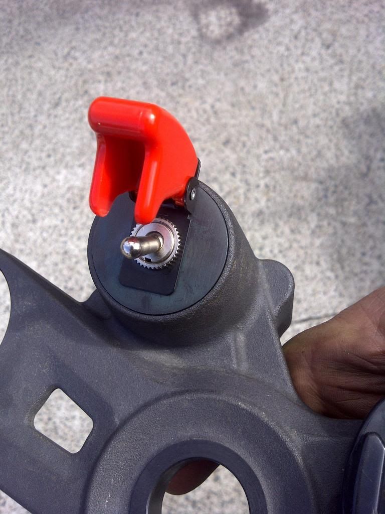
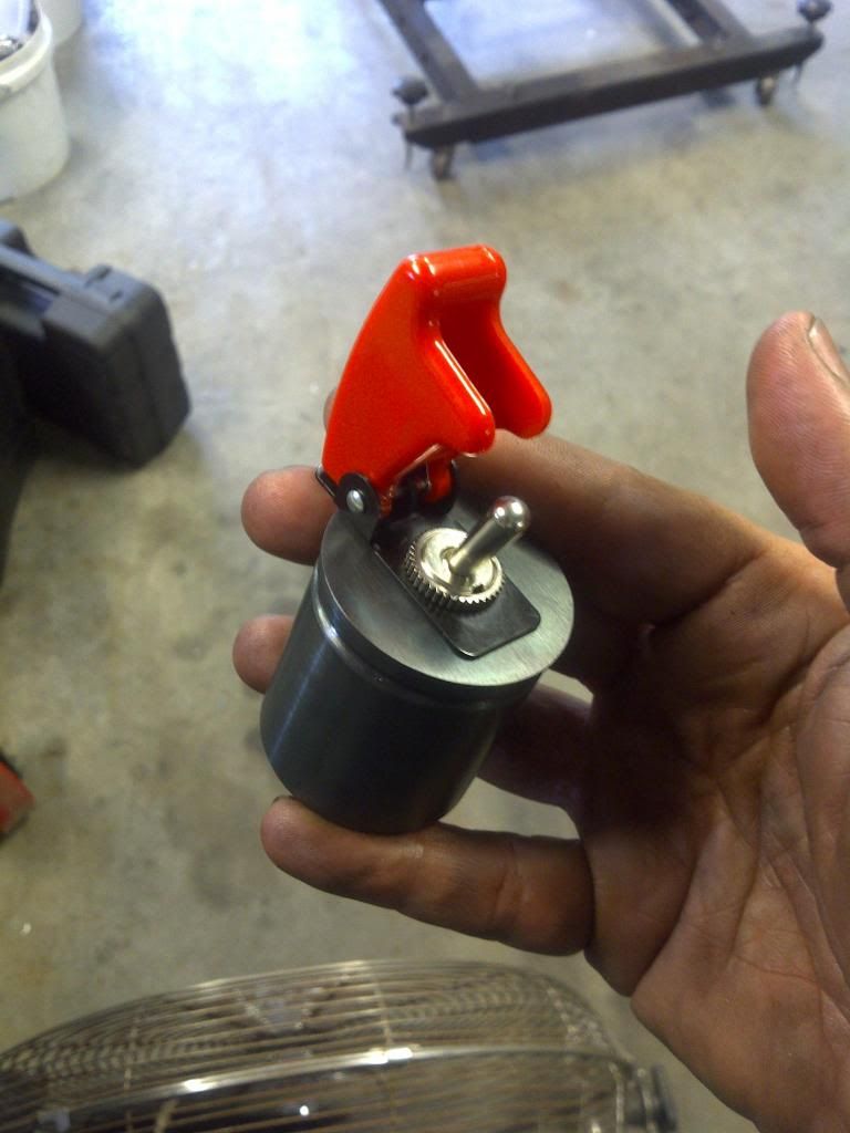
Since my bike is strictly tracked, I decided to delete the ignition. The following worked for me, and I found useful info on this site but do this at your own risk :D

The wires need to be found, cut, and spliced

at the ignition

brown... this is the wire that becomes energized when you turn the key on
it goes from the ignition to the 15a ignition fuse

White... this is the wire that supplies power to the ignition switch; it is energized even when the key is in the off position. It goes from the 30a main fuse to the ignition switch.

Gray... this is the wire that sends a "signal" to the ECU when the key is turned to the on position. This wire needs a 100-ohm 1/8-watt resistor spliced into it to "trick" the ECU into thinking you are using the keyed ignition to start the bike.

OPTIONAL red... I reused this wire so I could power the accessories that I use on the track, my GPS based lap timer, and my hi-def GoPro camera. This wire, in its normal state, energizes your left and right front city lights and, in the rear, your tail light and license plate light. It energizes when the key is turned to the on position.

at the start stop switch

Yellow/red wire... this wire supplies power to the start/stop switch. It comes from the 15a ignition fuse and is energized when you turn the key to the on position. It is energized regardless of the position of the start/stop switch.

Red wire... this wire becomes energized when the start/stop switch is in the start position. It goes to the fuel pump relay, coil wires, and to ECU.

o.k., let's start cutting...:buzzsaw:
 
#33 ·
That's why I have mine wired to a separate 30A toggle switch.
-Cody
 
#34 ·
Yea...

The proper way to do this would be wiring all this to a relay that is activated by the killswitch.

I would be surprized if this didnt fail at some point. I hope its not when you are leading a race! If I were you I'd think about wiring this setup through a relay.

I am doing mine by wiring it to a relay that is activated by a second bar mounted kill switch.


Sent from my GT-P3113 using Motorcycle.com Free App
 
#36 ·
Are there any write-ups for doing it using a separate toggle switch? I'd love to never have to deal with a key again on my track bike. Gas cap is no problem...but have been looking for a clean wait to go with a keyless ignition.

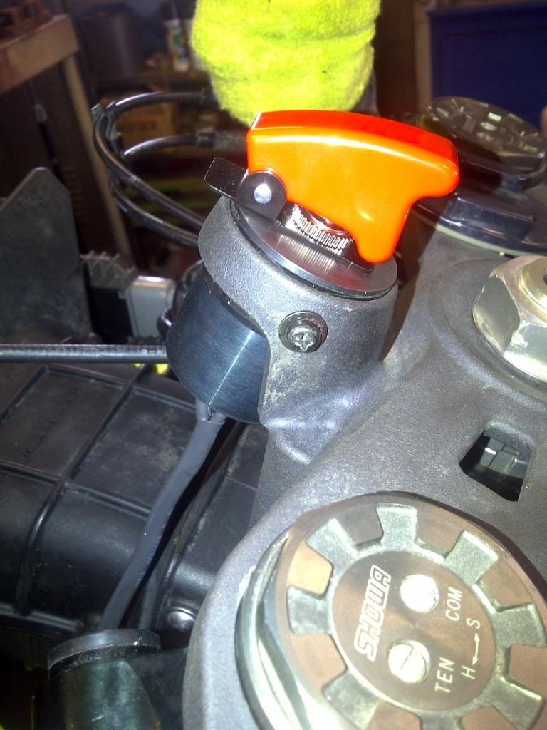
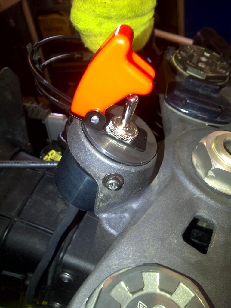
Would like to get rid of the ignition assembly all together and mount a switch in its place.
 
#37 · (Edited)
Trying to do this to mine but I'm stuck. Wiring isn't the same as the US models.

Ignition-BR
Battery-W
Tail 1-bl
Tail 2-r
W/G and w/bk aren't needed.

Using a toggle switch, tried connecting them all without a resistor, pump won't prime. Tried using a 100ohm 1/2w resistor from bl to br. Still a no go T_T any help would be great.

Would the fact that my model has immobilized be an issue?

Sent from Motorcycle.com Free App
 
#38 ·
If you have a chip in the key, it would definitely cause it not to start.
-Cody
 
#39 ·
From what I can tell from us models and outside us models are that outside models have an immobiliser and our keys are registered to the ecu. I think I may just have to rewire the ignition back in(hidden) and keep the key in and run a switch from the brown or white wire? Would this be safe?
 
#40 ·
I'd say so.
-Cody
 
#44 · (Edited)
fitted this up over the last couple of days into an Aussie model with immobiliser...

options are as follows:
1) relocate ignition under tank and wire in separate switch
2) get hold of US ECU and modify harness to accomodate the different wiring between the US and International models
3) get hold of US ECU and harness...

I couldnt get hold of a US harness so went with option 2...

My aim was to have the Harness and plugs as intact as possible so I could revert back to original setup if needed (ie - if it didnt work :) )

The Int. models don't have a grey wire due to the immobiliser being installed.. so the plan was to compare the 2 ECUs and Harnesses and chase what the int. Harness would do with the US ECU.

The grey wire is connected to the US ECU at the same place that the Int. ECU connects to the Immobiliser Amplifier (Blue/White wire). The Amplifier sits in the nose cone on the air intake, so conveniently positioned..


The resistor needs to go inline with the Blue/ White wire and have power connected to it. I did this with a supply from a red wire nearby that was previously for lights...

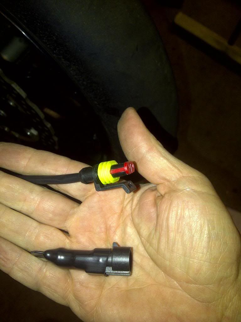
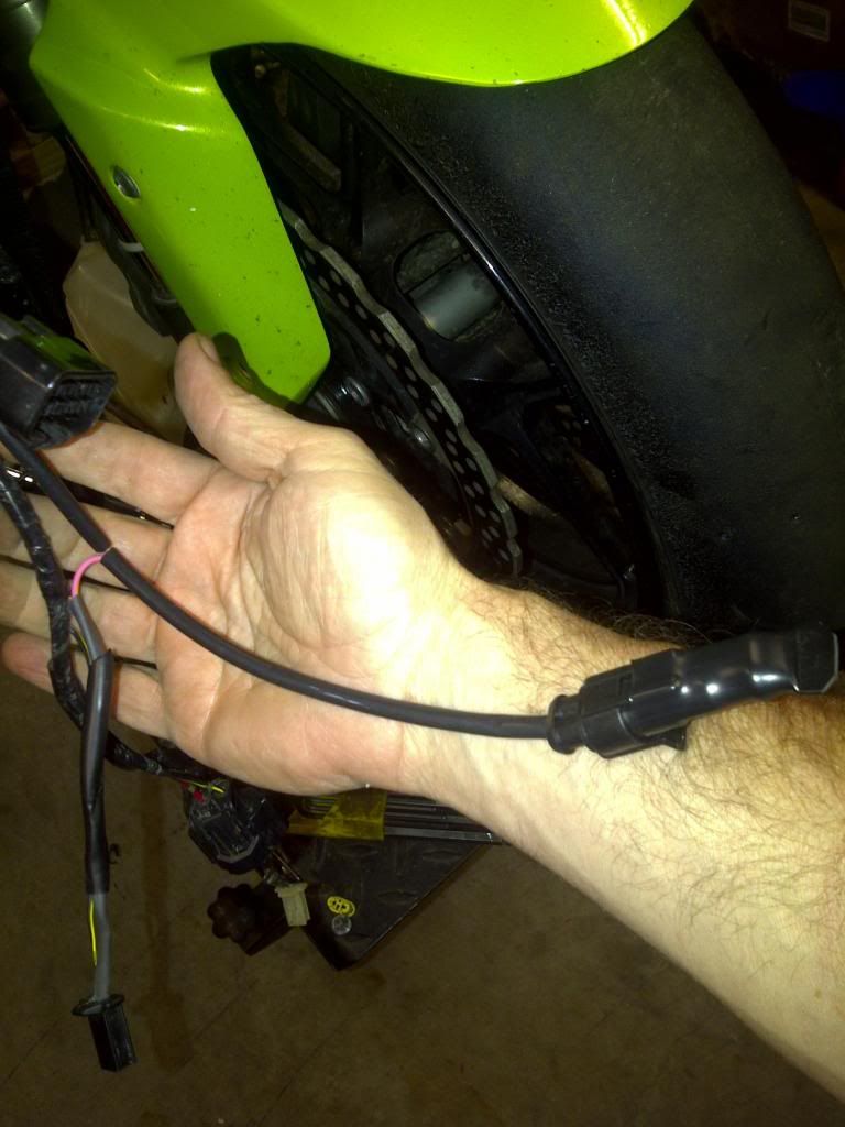
I didn't want to hard wire the resistor in place to make sure it was easily reversible, so I wired in a 2 pin plug that would have the power on one pin and the blue wire on the other.


Then I connected the resistor to a mating plug and inserted into the newly installed plug.


The next step was to connect the BRS to the main Harness. Again, not wanting to cut wires, and retain the original plug, I connected the white supply wire to one side of the BRS, and made a return leg from the BRS to the connector with 3 tails. The tails were connected to the Brown, Red and Red/ Blue wires. This would supply power to the main harness and the Accessories, giving both "On" and "Park" positions powered. While not totally necessary, I did this to give me power options around the bike in future as the park position power is on as well and save any stress later...

These were connected to the Harness Connector for the igniton with female spade lugs and heat shrunk in place..

Then reassembled the bike and good to go..


If ever I need to go back to the Int ECU, I can unplug the BRS at the ignition connector and plug in the original ignition, and remove the resistor by unplugging it from the new plug. Install the oem ECU and ready to roll...
 
#45 · (Edited)
Incase anyone wants to do this to a 2013 here are the wire colors to cross with the instructions in this post.
Ignition switch.
Blue-accessory power wire optional
Brown
Grey(resistor wire)
All go to
Red/wht on the start/stop switch (aka yellow/red in the instructions)

Ignition side white goes to the other red/wht on the start stop switch. (Aka "red" wire in the instructions)

Which red/wht is which you ask? The one in the middle location is the hot wire (known as yellow/red in instructions)
The other red/wht is located on a corner (not middle spot). This wire is the switched fuel pump (red) wire in the instructions

Besides that the brown/wht and the red/grn from the ignition switch plug side are the two you solder together. (aka yellow/red and red wires in instructions)
 
#46 ·
06 igntion delete and toggle switch

Hi, I know this is an old thread but I was reading the excellent write ups here for the ignition switch deletes for the ZX6 track bikes etc.
I am in the midst of doing this on my own 06 636 but wanted to incorporate a simple 30A toggle switch in place of the igntion switch,
Does anyone have any pointers on wiring for this?

I have tried sketching it out and have come up with the following, (please do not take this as correct as I have not tried it yet).

White from ignition block to toggle switch input
Add wire from toggle output and join to Yellow/Red kill switch wire
Gray wire with resistor and brown wires to Red kill switch wire
Cap off yellow/red and red wires from kill switch at plug side

Does this sound like it would work?
I am not planning on using auxilliaries etc so assume other wires to ignition can be deleted?

Any help/guidance welcome before I potentially fry my bike.
Thanks.
 
#54 · (Edited)
fyi woodcraft now manufacturers a plug and play harness that plugs into your existing wiring harness that deletes the ignition cylinder (you just power up everything via the killswitch, and hit the starter). Costs $50 and you don't have to hack up your wiring harness. Works great for me so far (for US models only, with no immobilizer):

https://www.woodcraft-cfm.com/cgi-bin/commerce.cgi?search=action&category=KSEH
 
#55 ·
Hello! :smile2:

I need to rewire the AU model wiring (ECU #21175-0188) w/ IMMO to the US model ECU #21175-0163 w/o IMMO.
I know about 100 Ohm resistor installed in the IgnitionLock between the Battery "+" (W) and (GY) to power the ECU w/o IMMOs. But there is no correct wiring diagrams in the Service manuals to find which Pin number of the ECU's connector the GREY (GY) wire goes to!

Can anybody help me to understand which ECU Pin I need to power up from 24Pin (BR, Ignition) to ??Pin (GY) with the resistor inline?
 
#58 ·
Out of curiosity, why not just leave the key in permanently? Perhaps glue the thing in place, since this is a bike that's only going to be used at the track and you're removing the little bit of security that the key provides anyways.
 
#61 ·
since my bike is strictly track i decided to delete the ignition. the following worked for me and i found useful info on this site but do this at your own risk:D

the wires needed to found, cut and spliced

at the ignition

brown... this is the wire that becomes energized when you turn the key to on
it goes from the ignition to the 15a ignition fuse

white... this is the wire that supplies power to the ignition switch, it is energized even when the key is in the off position. it goes from the 30a main fuse to the ignition switch

gray... this is the wire that sends a "signal" to the ecu when the key is turned to the on position. this wire needs a 100 ohm 1/8 watt resistor spliced into it to "trick" the ecu into thinking you are using the keyed ignition to start the bike

OPTIONAL red... i reused this wire so i can power my accessories that i use on the track, my gps based lap timer and hi def gopro camera. this wire in its normal state energizes your left and right front city lights and in the rear your tail light and license plate light. it energizees when the key is turned to the on position

at the start stop switch

yellow/red wire... this wire supplies power to the start/stop switch. it comes from the 15a ignition fure and is energized when you turn the key to the on position. it is energized regardless of the position of the start/stop switch

red wire... this wire becomes energized when the start/stop switch is in the start position. it goes to the fuel pump relay, coil wires, and to the ecu

o.k. lets start cutting...:buzzsaw:
Ciao.. great job ... but does it also work on European models? I have a 2010 zx6r (bike sold in Italy) with the immobilzer active in the original ECU and I would like to make this modification on my bike ... Can I do it? thank you